- 您现在的位置:买卖IC网 > Sheet目录307 > ADE7758ARWZRL (Analog Devices Inc)IC ENERGY METERING 3PHASE 24SOIC
�� �
�
�(� 10� 2� ×� 3885.68� 2� )� –� (� 0� .� 260� 2� ×� 148242.2� 2� )� =�
��
�(� 0� .� 260� –� 10� 2� )�
�(� 220� ×� 86362.36� )� –� (� 25� ×� 744570.8� )� =� ?� 30� .� 9� =� ?� 31� =� 0xFE1�
��
�(� 25� –� 220� )�
�Data Sheet�
�Step� 1:� Set� configuration� registers� for� zero� crossings� on� all�
�phases� by� writing� the� value� 0x38� to� the� LCYCMODE� register�
�(0x17).� This� sets� all� of� the� ZXSEL� bits� to� Logic� 1.�
�Step� 2:� Set� the� interrupt� mask� register� for� zero-crossing�
�detection� on� all� phases� by� writing� 0xE00� to� the� MASK[0:24]�
�register� (0x18).� This� sets� all� of� the� ZX� bits� to� Logic� 1.�
�Step� 3:� Set� up� the� calibration� system� for� one� of� the� two� test�
�conditions:� I� TEST� and� V� NOM� ,� and� I� FULLSCALE� /500� and� V� FULLSCALE� /20.�
�Step� 4:� Read� the� rms� registers� after� the� zero-crossing� interrupt�
�and� take� an� average� of� N� samples.� This� is� recommended� to� get�
�the� most� stable� rms� readings.� This� procedure� is� detailed� in�
�Figure� 85:� Steps� 4a� through� 4e.�
�Step� 4a.� Choose� the� number� of� samples,� N,� to� be� averaged.�
�Step� 4b.� Reset� the� interrupt� status� register� by� reading� RSTATUS�
�(0x1A).�
�Step� 4c.� Wait� for� the� zero-crossing� interrupt.� When� the� zero-�
�crossing� interrupt� occurs,� move� to� Step� 4d.�
�Step� 4d.� Read� the� xIRMS� and� xVRMS� registers.� These� values�
�will� be� averaged� in� Step� 4e.�
�Step� 4e:� Average� the� N� samples� of� xIRMS� and� xVRMS.� The�
�averaged� values� will� be� used� in� Step� 5.�
�Step� 5:� Write� to� the� xVRMSOS� (0x33� to� 0x35)� and� xIRMSOS�
�(0x36� to� 0x38)� registers� according� to� the� following� equations:�
�ADE7758�
�Twenty� readings� are� taken� synchronous� to� the� zero� crossings� of�
�all� three� phases� at� each� current� and� voltage� to� determine� the�
�average� xIRMS� and� xVRMS� readings.� At� I� TEST� and� V� NOM� ,� the�
�example� ADE7758� meter� gets� an� average� AIRMS� (0x0A)�
�reading� of� 148242.2� and� 744570.8� in� the� AVRMS� (0x0D)�
�register.� Then� the� current� is� set� to� I� MIN� =� I� FULLSCALE� /500� or�
�260� mA.� At� I� MIN� ,� the� average� AIRMS� reading� is� 3885.68.� At�
�V� MIN� =� V� FULLSCALE� /20� or� 25� V,� the� example� meter� gets� an� average�
�AVRMS� of� 86362.36.� Using� this� data,� ?15d� is� written� to�
�AIRMSOS� (0x36)� and� ?31d� is� written� to� AVRMSOS� (0x33)�
�registers� according� to� the� Equation� 77� and� Equation� 78.�
�AIRMSOS� =�
�1�
�16384�
�?� 14� .� 8� =� ?� 15� =� 0xFF2�
�AVRMSOS� =�
�1�
�64�
�This� example� shows� the� calculations� and� measurements� for�
�Phase� A� only.� However,� all� three� xIRMS� and� xVRMS� registers�
�can� be� read� simultaneously� to� compute� the� values� for� each�
�xIRMSOS� and� xVRMSOS� register.�
�1� (� I� 2� ×� IRMS� IMIN� 2� )� –� (� I� MIN� 2� ×� IRMS� ITEST� 2� )�
�xIRMSOS� =�
�� TEST�
�16384� I� MIN� 2� –� I� TEST� 2�
�where:�
�I� MIN� is� the� full� scale� current/500.�
�I� TEST� is� the� test� current.�
�IRMS� IMIN� and� IRMS� ITEST� are� the� current� rms� register� values�
�without� offset� correction� for� the� inputs� I� MIN� and� I� TEST� ,�
�respectively.�
�xVRMSOS� =�
�(77)�
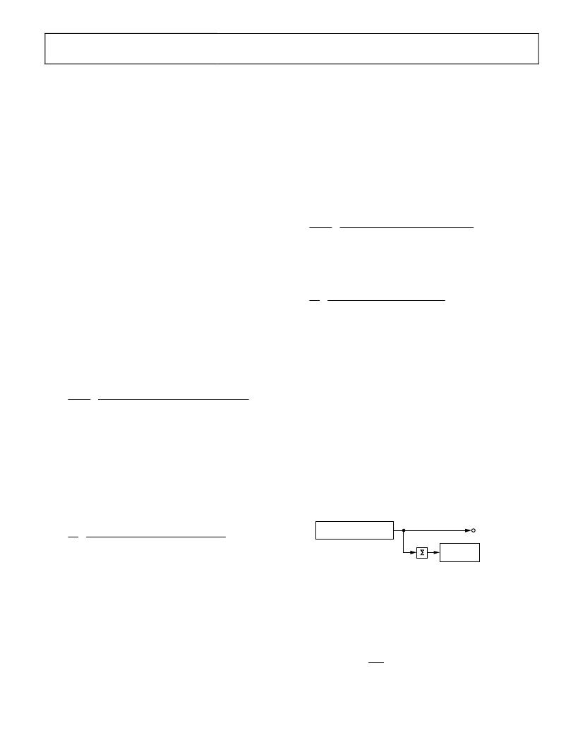
�CHECKSUM� REGISTER�
�The� ADE7758� has� a� checksum� register� CHKSUM[7:0]� (0x7E)�
�to� ensure� the� data� bits� received� in� the� last� serial� read� operation�
�are� not� corrupted.� The� 8-bit� checksum� register� is� reset� before�
�the� first� bit� (MSB� of� the� register� to� be� read)� is� put� on� the� DOUT�
�pin.� During� a� serial� read� operation,� when� each� data� bit� becomes�
�available� on� the� rising� edge� of� SCLK,� the� bit� is� added� to� the�
�checksum� register.� In� the� end� of� the� serial� read� operation,� the�
�contents� of� the� checksum� register� are� equal� to� the� sum� of� all� the�
�1s� in� the� register� previously� read.� Using� the� checksum� register,� the�
�user� can� determine� if� an� error� has� occurred� during� the� last� read�
�operation.� Note� that� a� read� to� the� checksum� register� also�
�generates� a� checksum� of� the� checksum� register� itself.�
�� NOM�
�1�
�64�
�where:�
�V�
�×� VRMS� VMIN� –� V� MIN� ×� VRMS� VNOM�
�V� MIN� –� V� NOM�
�(78)�
�CONTENT� OF� REGISTERS�
�(N-BYTES)�
�CHECKSUM�
�REGISTER�
�DOUT�
�ADDR:� 0x7E�
�V� MIN� is� the� full� scale� voltage/20�
�V� NOM� is� the� nominal� line� voltage.�
�VRMS� VMIN� and� VRMS� VNOM� are� the� voltage� rms� register� values�
�without� offset� correction� for� the� input� V� MIN� and� V� NOM� ,�
�respectively.�
�Example:� Calibration� of� RMS� Offsets�
�For� this� example,� I� TEST� =� 10� A,� I� MAX� =� 100� A,� V� NOM� =� 220� V,�
�V� FULLSCALE� =� 500� V,� Power� Factor� =� 1,� and� Frequency� =� 50� Hz.�
�Figure� 86.� Checksum� Register� for� Serial� Interface� Read�
�INTERRUPTS�
�The� ADE7758� interrupts� are� managed� through� the� interrupt�
�status� register� (STATUS[23:0],� Address� 0x19)� and� the� interrupt�
�mask� register� (MASK[23:0],� Address� 0x18).� When� an� interrupt�
�event� occurs� in� the� ADE7758� ,� the� corresponding� flag� in� the�
�interrupt� status� register� is� set� to� a� Logic� 1� (see� Table� 24).� If� the�
�mask� bit� for� this� interrupt� in� the� interrupt� mask� register� is�
�Logic� 1,� then� the� IRQ� logic� output� goes� active� low.� The� flag� bits�
�Rev.� E� |� Page� 55� of� 72�
�发布紧急采购,3分钟左右您将得到回复。
相关PDF资料
ADE7761AARSZ-RL
IC ENERGY METERING 1PHASE 20SSOP
ADE7761BARSZ-RL
IC ENERGY METERING 1PHASE 20SSOP
ADE7768ARZ-RL
IC ENERGY METERING 1PHASE 16SOIC
ADE7769ARZ-RL
IC ENERGY METERING 1PHASE 16SOIC
ADM8843ACPZ-REEL7
IC LED DRVR WHITE BCKLGT 16LFCSP
ADP1653ACPZ-R7
IC LED DRVR PHOTO FLASH 16-LFCSP
ADP1712-EVALZ
BOARD EVALUATION ADP1712
ADP1720-EVALZ
BOARD EVAL FOR ADP1720-ADJ
相关代理商/技术参数
ADE7759
制造商:AD 制造商全称:Analog Devices 功能描述:Active Energy Metering IC with di/dt Sensor Interface
ADE7759ARS
功能描述:IC ENERGY METERING 1PHASE 20SSOP RoHS:否 类别:集成电路 (IC) >> PMIC - 能量测量 系列:- 产品培训模块:Lead (SnPb) Finish for COTS
Obsolescence Mitigation Program 标准包装:2,500 系列:*
ADE7759ARSRL
功能描述:IC ENERGY METERING 1PHASE 20SSOP RoHS:否 类别:集成电路 (IC) >> PMIC - 能量测量 系列:- 产品培训模块:Lead (SnPb) Finish for COTS
Obsolescence Mitigation Program 标准包装:2,500 系列:*
ADE7759ARSZ
功能描述:IC ENERGY METERING 1PHASE 20SSOP RoHS:是 类别:集成电路 (IC) >> PMIC - 能量测量 系列:- 产品培训模块:Lead (SnPb) Finish for COTS
Obsolescence Mitigation Program 标准包装:2,500 系列:*
ADE7759ARSZRL
功能描述:IC ENERGY METERING 1PHASE 20SSOP RoHS:是 类别:集成电路 (IC) >> PMIC - 能量测量 系列:- 产品培训模块:Lead (SnPb) Finish for COTS
Obsolescence Mitigation Program 标准包装:2,500 系列:*
ADE7760
制造商:AD 制造商全称:Analog Devices 功能描述:Energy Metering IC with On-Chip Fault Detection
ADE7760ARS
制造商:Analog Devices 功能描述:Energy Measurement 20-Pin SSOP 制造商:Analog Devices 功能描述:ENERGY METER IC W/ ONCHIP FAULT & OSCIL. - Rail/Tube
ADE7760ARSRL
制造商:Analog Devices 功能描述:Energy Measurement 20-Pin SSOP T/R 制造商:Analog Devices 功能描述:ENERGY METER IC W/ONCHIP FAULT & OSCIL. - Tape and Reel